Introduction
TL494 is a widely known PWM controller for SMPS. However, it is an old bipolar transistor integrated circuit and only a few SPICE models are available. The major drawback of SPICE for SMPS design is the duration of the simulation. Nevertheless, other simulations approach based on state space modeling exist.
Personally, I use SIMPLIS (https://simplis.com/product/simplis). This software is able to simulate complex circuits by modeling electronic circuit behavior thanks to piecewise linear (PWL) approach. After circuit start-ups, a periodic operating point (POP) may be found, and the simulator provide you few switching cycles of the simulated circuit. Moreover, if a POP exists, SIMPLIS can linearize it and compute the transfer function. According to the SIMPLIS website, it’s at least 10 times faster than SPICE simulations to find the transfer function of SMPS under simulations. That makes it easier SMPS design !
Why TL494 ?
TL494 is now (in 2026) a cheap IC (roughly 0.20€), multi-manufactured (at least Texas Instruments and OnSemi), available in a wide range of packages (from DIL to TSSOP) and multi-topologies (Flyback, buck, boost, forward …). Lots of applications notes, schematics and articles have been writing on it. All of this make it suitable for home prototyping, education and industrial use.
TL494 description
TL494 is a very simple SMPS controller. Let’s start by analyzing the architecture thanks to the following diagram (copy and pasted from OnSemi datasheet (https://www.onsemi.com/download/data-sheet/pdf/tl494-d.pdf).
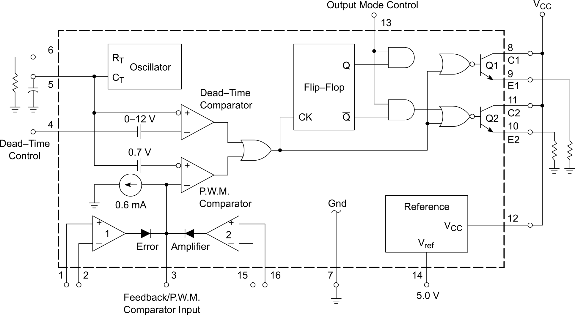
Oscillator provides a sawtooth signal on the net “CT.” This signal is used to generate the PWM signal by comparing it to the “Feedback” signal. “CT” is also used to set up an inhibition signal at each edge by comparing it to “Dead-Time Control” (DC voltage is directly proportional to the dead time). The OR gate synthesize real PWM signals from the ideal one and inhibition signal and feed into the output logic.
TL494 has been designed for single or push-pull power transistor configuration to address a wide variety of topologies. For a single power transistor topology, duty cycle needs to vary from 5% to 95% (dead times taken into account) but for half bridge, the half is required. This adjustment is made by the output logic stage made of few logic gates (1 flip-flop, 2 AND , 2 NOR).
Once again, to be as flexible as possible, the output stage is not a basic push-pull but a pseudo-transistor switch. By wiring it in common emitter or common collectors, the signal can be easily inverted without the need of logic gates. Also, the high current capability (200 mA) makes it suitable to drive directly power transistors as proposed in the typical application in the datasheet.
To finish, a voltage reference and operational amplifiers (opamp) are embedded to complete the minimum set of function to control a DC/DC converter. They are used to close the control loop. Only one opamp is needed for output voltage feedback, but the second opamp can be used to implement an output current limit. In both cases, output voltage is subtracted from the reference voltage and then amplified and integrated to make proportional integral (PI) also called type-II corrector. The output of amplifiers is also the output of the corrector and the input of PWM comparator. In other words, it is the “Feedback” signal. By the way, the loop is closed!
Modeling
Modeling an IC in SIMPLIS is close to reverse engineering. Through knowledge of IC architecture, it is easy to draw the following schematic (PDF version available in section Downloads).
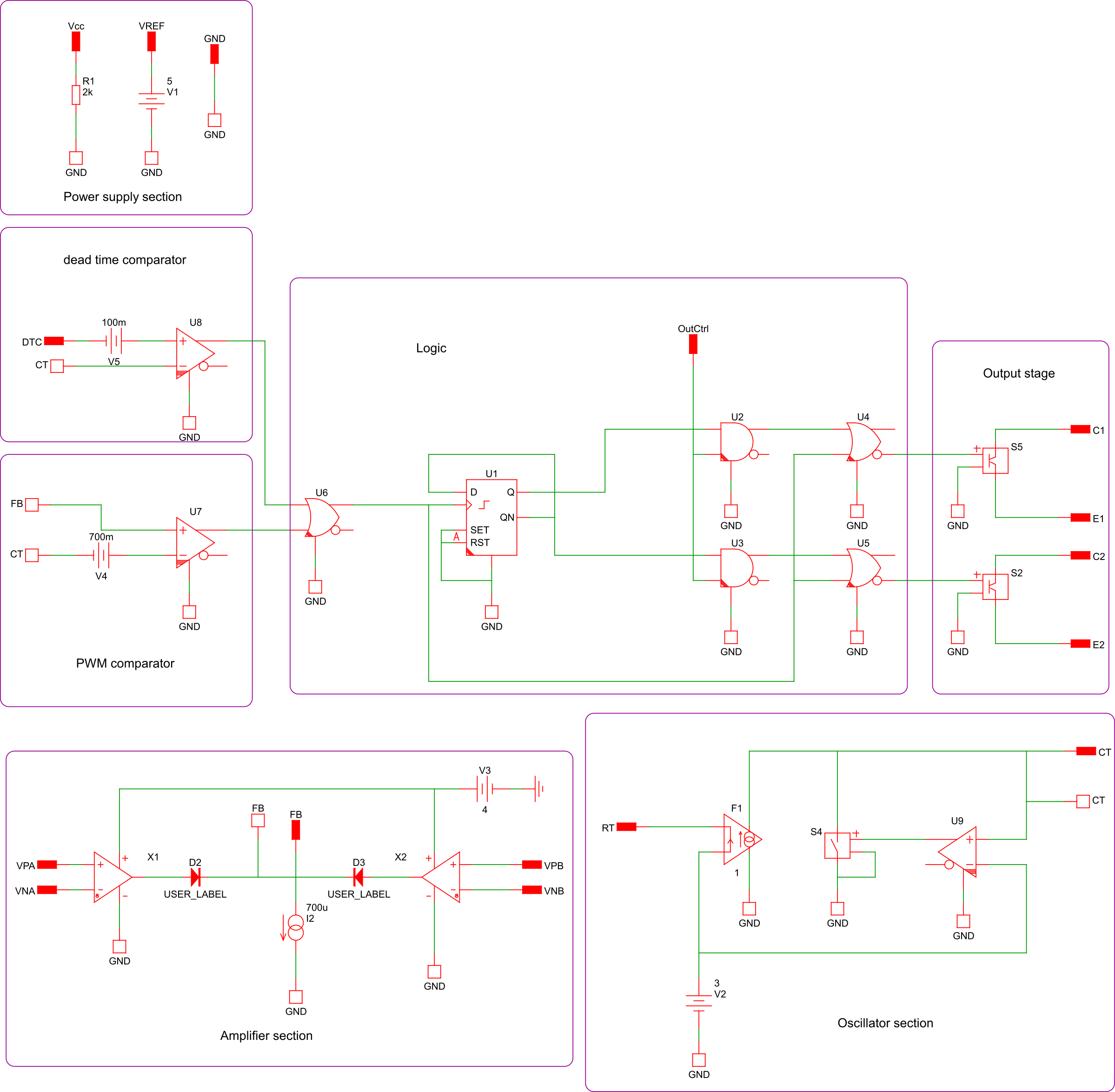
Keep in mind, it’s a behavioral model, not an electronic model ! As a consequence, the model will be taken into account what you want to model. For instance, I use SIMPLIS to verify topology choice, compute waveforms and check converter stability in closed loop. To do that, complete modeling is not required. Here, I consider voltage reference as perfect and I model it by a voltage source. Once again, I don’t care of opamp power supply rejection ration (PSRR). I put 100 nF capacitor across power supply pins and I check during prototyping that the supply voltage seems good (less than 1% ripple). If these imperfections matter in your simulation bench, add it to the model. Following behaviors are modeled:
- Opamp (offset, slew rate, bandwidth limit and output voltage saturation)
- Output stage (output current limit, voltage drop, rise and fall time)
- logic gates (propagation time, rise and fall time)
- Comparators (offset, delay time, rise and fall time)
Drawing the model is easy thanks to the datasheet architecture. However, it becomes harder when we need to give values at each building blocks. Some values can be found in datasheet (output voltage reference, opamp offset …). Some others not. In this case, one way is trying to figure them out from high-level datasheet values such as min or max duty cycle. It remains hard because min or max duty cycle is not related to one building block but a cocktail of factors. Putting typical values of bipolar IC performance is also a good way. Another solution is compared to a reference SPICE model or demo board measurement. Here, I choose SPICE model.
SIMPLIS model, symbol and test bench are available in section Downloads.
Spice model comparison
I found a good SPICE model for LTSpice here (https://github.com/sunnyiisc/Spice-Model-Collections/blob/main/TL494.sub). I choose the reference design from Texas Instruments (https://www.ti.com/lit/an/slva001e/slva001e.pdf) as a test vehicle. Moreover, this document gives lots of insights about TL494 working principle.
Following figure presents TL494 test bench for SIMPLIS and SPICE simulations. Few aspects have been adapted in SPICE simulations. S1 becomes P channel MOSFET and POP trigger has been removed.
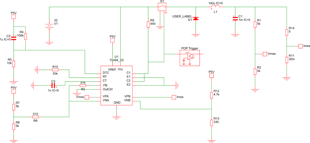
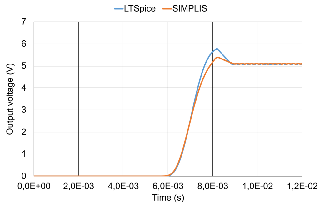
The following graph compares converter start-up for the two software and models under test. Be careful when comparing SPICE and SIMPLIS. In SPICE, a real MOSFET is implemented whereas it is a switch in SIMPLIS. Moreover, this converter start thanks to a soft start circuit (R4 and C2) which reduce the maximum duty cycle at the beginning to avoid large peak current in MOSFET, inductor and output capacitor. Without soft start, power transistor may be destroyed.
For startup waveforms, I consider matching between SPICE and SIMPLIS good. Further model validation will be done by prototyping.
Conclusion
TL494 now has a SIMPLIS model useful to reduce simulation time and make design easier. However, be aware of limits (no experimental validation and some values implemented in SIMPLIS model comes from literature about bipolar IC, it is not a measurement or datasheet values).
If you have any remarks or suggestions to improve SIMPLIS model, please tell me !
Related links
Texas Instrument TL494 web page: https://www.ti.com/product/TL494
OnSemi TL494 web page: https://www.onsemi.com/products/power-management/dc-dc-power-conversion/controllers/tl494
Github page of the reference SPICE model: https://github.com/sunnyiisc/Spice-Model-Collections/blob/main/TL494.sub
TL494 reference design from fotoelektronika: https://fotoelektronika.com/wp-content/uploads/2024/08/tl494-spice-model.pdf
TL494 reference design from Texas: https://www.ti.com/lit/an/slva001e/slva001e.pdf
Leave a Reply